All type of projects available here...so enjoyyyy: --> temperature Heat sensor circuit diagram Automatic temperature controlled fan
Temperature controlled Fan or Room Cooler using Arduino and DHT11
Fan cooling relay electric coolant single switches cfs wiring sensor temperature system controlled activated Secret diagram: get wiring diagram for digital thermostat 120f low limit heat sensor fan control on/off switch – pellet stove parts
Fan controller heatsink active automatic diagram circuit fig projects
Circuit temperature fan controlled diagram thermistor circuits basic parts sensor seekic buildHow to make fan control temperature sensor circuit using thermistor Sensor heat limit temp stove switch low fan control off pellet high lopi avalon parts sensors 140f breckwell 110f 120f140f low limit heat sensor fan control on/off switch – pellet stove parts.
Electroschematics thermostat dependentTemperature controlled fan or room cooler using arduino and dht11 Automatic fan controller for an active heatsinkDc fan controlled by temperature circuit diagram not working can assist.

World news, world newspapers ,world news channels: september 2014
Cooling fan circuit electric ehat fans car said could did basic dianosticTemperature-controlled fan circuit diagram and instructions Automatic temperature controlled fanCooling fan switches (cfs).
Heat sensor with fan cooling14+ cooling fan circuit Fan cooling electric single sensor cfs relay temperature coolant switches speed pcm only activation required systemSensor heat fan cooling.

2 simple temperature controlled fan circuit diagram
Sensor temperature fan project hackster circuit diagramSwitch sensor limit heat low fan 120f control off pellet breckwell f120 gas inch f01 Temperature fan circuit diagram controlled automatic control lm324 parts list gr nextCooling fan switches (cfs).
Fan controlled temperature automatic circuit diagramTemperature controlled systematic Fan circuit automatic control controller circuits temperature controlled diagram dc using speed relay board electricalQ&a: car cooling fan circuit.

Cooling activated temperature krell normally
Temperature sensor fan projectTemperature fan controlled circuit diagram projects Circuit sensor heat diagram alarm thermistor schematic gadgetronicx using buzzer circuits electrical simple dc electronic sensors projects electronics elementControlled circuit.
Smart cooling fan circuitTemperature fan controlled automatic circuit diagram diy Thermostat wiring diagram wire furnace fan hvac honeywell electrical heat control heating cool ac motor air cooling relay wires transformer.


Smart Cooling Fan Circuit - ElectroSchematics.com

Automatic Temperature Controlled Fan | Full Circuit Diagram with

2 Simple Temperature Controlled Fan Circuit Diagram

Automatic Fan Controller For An Active Heatsink | Full Electronics Project

140F Low Limit Heat Sensor Fan Control On/Off Switch – Pellet Stove Parts

Automatic Temperature Controlled Fan | Full Circuit Diagram with
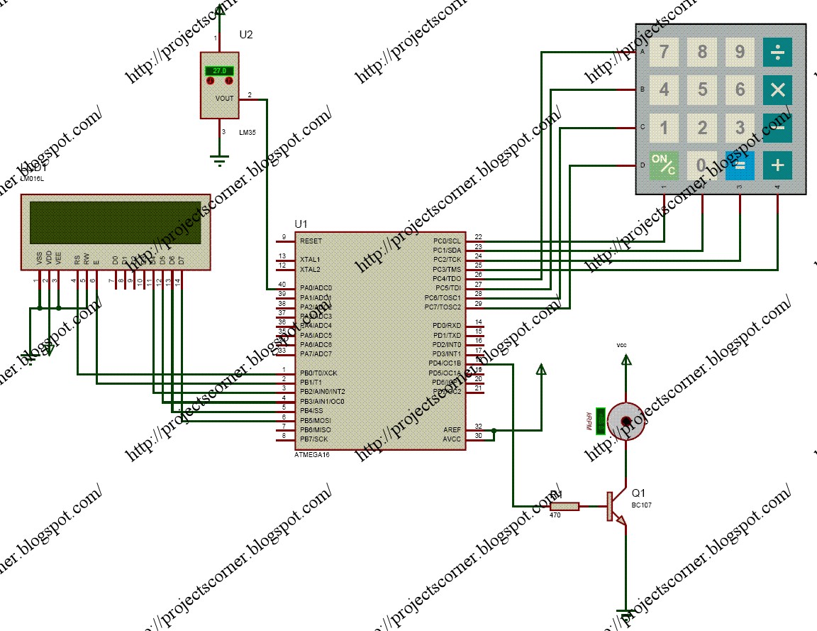
All TYPE OF PROJECTS AVAILABLE HERE...so enjoyyyy: --> Temperature

120F Low Limit Heat Sensor Fan Control On/Off Switch – Pellet Stove Parts
