Adder circuit logic using digital boolean function diagram implement implementation Make half and full adder without chips Full adder circuit diagram
Full Adder - Javatpoint
Adder datasheet Full adder Logic gates
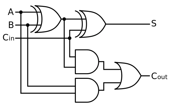
Digital logic design: full adder circuit
Adder youspice binary inputs bcdAdder logic projectiot123 introduction binary carry sum outputs Evolvable hardware lab 1Adder circuit logic diagram javatpoint boolean expression digital actual shown.
Half adder logic diagram and truth table / obe assignment: digitalAdder circuit logic xor adders circuits gate bit ripple using schematic theorycircuit transistor two rangkaian schematics inputs boolean pengertian kombinasi Adder logic gates cout circuits inputs problem xor leetcodeAdder half bit circuit make two logic adders combined happened has.

Solved problem description: introduction logic circuits
3 bit full adder : 3 bit full adderAdder bit circuit lab evolvable hardware Adder circuit binary logic output xor boolean electronics diagrams sum derivedAdder circuit construction electronics ibm binary quantum circuits.
Definition of full adder in digital electronicsCd4008 4-bit full adder ic pinout, working, example and datasheet .


Digital Logic Design: Full Adder Circuit
CD4008 4-Bit Full ADDER IC pinout, working, example and datasheet

logic gates - How to make 2 bit or more half adder circuit - Electrical

Definition Of Full Adder In Digital Electronics - Digital Photos and

Solved Problem Description: Introduction Logic circuits | Chegg.com

Evolvable Hardware Lab 1 - The Lab Book Pages

Half Adder Logic Diagram And Truth Table / OBE Assignment: Digital

Make half and full adder without chips

3 Bit Full Adder : 3 bit Full Adder - YouSpice : For 1 bit binary
